
A useful tool for offline tinkering when away from your devices
At Remote Flags we were recently tasked to build an IoT platform to manage and interact with IOT devices. These IOT devices would run with Revolution Pi, which is based on Raspberry Pi.
We didn't have access to their hardware, neither physically nor logically through a network communication protocol.
To facilitate new feature development as well as doing end-to-end testing, we decided to build a simulator, to mirror the hardware behavior when receiving and sending messages.
This solution described in this post uses the Revolution Pi software, revpimodio2, written in Python.
Initial implementation
At first, our plan was to write the same code as installed on the device, but abstracting the low levels details, and creating custom made implementations.
An example of such an implementation would be simulating a LED turning on and off. In the hardware itself you would see the light switching on and off, but in the simulator that would simply be a boolean changing value accompanied by a log message.
We did some initial testing and this approach worked, although it wasn't a perfect solution. In terms of software development, this would specific code for each hardware component: things like, what type of values does a component support? is it connected to an input or output pin? what are the upper and lower bound limits for the hardware? This is a lot of logic that needs to be implemented that exists out of the box on software for handling IOT hardware, such as Revolution Pi.
Diving deeper, we've found Revolution Pi offers a simulation mode within their software. It did not do what we expected, but we found interesting details that ended up being extremely useful.
Revolution Pi RevPiModIO
Here's the documentation. The main class used when programming with Revolution Pi is revpimodio2.RevPiModIO.
There are details about most fields from its constructor, including a simulation field.
The simulation parameter we expected to help on this challenge lacks documentation: what is in there says: NOTE: Parameter ‘monitoring’ and ‘simulator’ are not available here because they are set automatically..
There were also some other undocumented parameters in the documentation, namely procimg and configrsc. These would be the key for our solution.
While we were searching for more information for this module, we encountered this forum post talking about a similar problem to what we were facing. In the post, there is mention of using a config.rsc to describe the hardware and a procimg as a process Image file.
Starting a simulated device
Armed with this information, we can start implementing a software simulator with no hardware.
You will need to install revpimodio2 with pip: pip install revpimodio2.
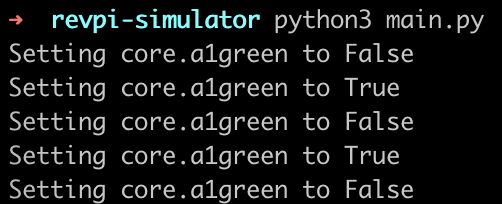
Here's a script to initialize the simulator and then toggle a simulated LED on and off every 5 seconds:
import revpimodio2
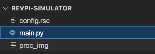
CONFIG_RSC_FILE = "config.rsc"
PROC_IMG_FILE = "proc_img"
def toggle_led(led_name, value):
print(f"Setting {led_name} to {not value}")
rpi.core.a1green.set_value(not value)
rpi = revpimodio2.RevPiModIO(
configrsc=CONFIG_RSC_FILE, procimg=PROC_IMG_FILE, autorefresh=True
)
rpi.core.a1green.reg_timerevent(toggle_led, 5000, prefire=True)
rpi.mainloop()
This creates an instance of RevPiModIO using the hardware layout and properties defined in CONFIG_RSC_FILE. The config.rsc file can be downloaded from a real configured device, so you can use a clone of the real hardware in terms of the layout, pins, and other definitions.
When started, the instance stores the initial state + any changes to the simulated software in
PROC_IMG_FILE. You need to create an empty file with the same name to begin, in this case proc_img.
The autorefresh parameter tells the software to update the process image automatically.
As for rpi.core.a1green.reg_timerevent(toggle_led, 5000, prefire=True), it calls the toggle_led function every 5 seconds.
rpi.mainloop() starts an infinite loop where the simulated device is turned on.
After this base setup, you're free to play with the rpi instance as if it were a real device: set values, setup event listeners, toggle LEDs, check status.
State is kept in the process image, so it is persisted between executions.
For help with this and other software-related tasks, consider working with us at Remote Flags!